![]() |
![]() |
| Test Equipment Catalog | Specials | Repair | Surplus | Ordering/Contact Info |
|
|
<< Ametek Advanced Temperature Calibrator Index
Ametek ATC650B Advanced Temperature |
||||||||||||||||||||||||||||||||||||||||||||||||||||||||||||||||||||||||||||||||||||||||||||||||||||||||||||||||||||||||
|
||||||||||||||||||||||||||||||||||||||||||||||||||||||||||||||||||||||||||||||||||||||||||||||||||||||||||||||||||||||||
|
||||||||||||||||||||||||||||||||||||||||||||||||||||||||||||||||||||||||||||||||||||||||||||||||||||||||||||||||||||||||
|
The Ametek ATC series (Advanced Temperature Calibrators
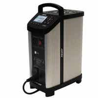
) combines the
accuracy of laboratory temperature sources with the speed and
portability of field dry-block calibrators. The unique dual-zone design
sets new standards for optimum temperature performance bin dry-block
calibrators. The Ametek ATC-650 all features the unique dual-zone heating block - designed for optimum performance and superior temperature homogeneity throughout the block. This new design has a performance equivalent to a liquid temperature bath. The ATC-157 features the widest temperature range for a cooling dry-block on the market today. Each ATC dry-block calibrator may be used to perform fully automatic calibration routines without using an external computer. Use the computer for full upload and download capabilities. Units may also be supplied with inputs for external reference sensors and for sensors-under-test. All ATC calibrators feature RS232 serial communication and standard delivery also includes the JOFRACAL calibration PC software. The ATC series of calibrators provide precision temperature calibration of sensors; whatever the type or format. This is accomplished through an innovative dual-zone heating technology. The Ametek ATC-650 all feature a dual-zone heating technology. Each heating zone is independently controlled for precision temperature calibration. The homogeneity in the lower part is close to that of a laboratory liquid bath. The lower zone ensures optimum heat dissipation throughout the entire calibration zone. The upper zone compensates for heat loss from the sensor-under-test and from the open top. This design also eliminates the need for insulation of the sensors-under-test and makes it possible to calibrate liquid-filled and other mechanical sensors. |
||||||||||||||||||||||||||||||||||||||||||||||||||||||||||||||||||||||||||||||||||||||||||||||||||||||||||||||||||||||||
|
MVI - Improved temperature stability MVI stands for ’’Mains power Variance Immunity’’. Unstable mains power supplies are a major contributor to on-site calibration inaccuracies. Traditional temperature calibrators often become unstable in production environments where large electrical motors, heating elements, and other devices are periodically cycled on or off. The cycling of supply power can cause the temperature regulator to perform inconsistently leading to both inaccurate readings and unstable temperatures. The Ametek ATC-650 calibrators employ the MVI, thus avoiding such stability problems. The MVI circuitry continuously monitors the supply voltage and ensures a constant energy flow to the heating elements. Highest accuracy ATC series calibrators may be supplied with a built-in reference thermometer for use with an external sensor. This feature allows one instrument to provide the freedom and flexibility to perform calibrations at the process site while maintaining a high accuracy. A special 90° angled external reference sensor has been designed to accommodate sensors with a transmitter head, top connector or similar arrangement. The user can decide whether to read the built-in reference sensor or the more accurate angled reference sensor from the calibrator’s large, easy-to-read LCD display. The external sensor and the internal sensor are independent of one another. Downloading of reference sensor linearization is done via a personal computer. SET-Follows-TRUE Available on the ATC650B, the “SET-Follows TRUE” makes the instrument tune in until the temperature of the external reference “TRUE” meets the desired “SET” temperature. This is used when it is critical that the temperature of the calibration zone matches the desired temperature when measured with accurate external reference sensors. This feature is ideal when calibrating gas correctors or other custody transfer applications. It is also extremely useful to calculation procedures. Reading of sensor-under-test The ATC650 is equipped with built-in converters (inputs) that enables measurement of virtually any type of temperature sensor including:
|
||||||||||||||||||||||||||||||||||||||||||||||||||||||||||||||||||||||||||||||||||||||||||||||||||||||||||||||||||||||||
|
Switch test Users may perform a thermo switch test and find “Open”, “Closed” and the hysteresis (deadband) automatically. The instrument retains the last five tests. Easy-to-use, intuitive operation All instrument settings can be performed from the front panel. The heat source is positioned away from the panel which helps protect the operator. The ATC keyboard is equipped with five, positive feedback function keys. They correspond to the text in the display and change functionality based on instrument operations. There are also dedicated function keys with permanent functions. The easy-to-read, backlit display is large with a high contrast that is readable even in high ambient light conditions. The display is easily read from all angles and from a distance without parallax problems. The display also features icons which help identifying instrument conditions and operational steps, making it more intuitive to work with. Set temperature The “Set temperature” feature allows the user to set the exact desired temperature with a resolution of 0.01°. Enhanced stability A stability indicator shows when the ATC calibrator has reached the desired temperature and is stable. The user may change the stability criteria, external reference and the sensor-under-test quickly and simply. The stability criteria is the user’s security for a correct calibration. A count-down timer is displayed next to the temperature read-out. Instrument setups The ATC series allows the user to store up to nine (9) complete instrument setups. You may store all sorts of information including temperature units, stability criteria, use of external reference sensor, resolution, sensor-under-test (SUT), conversion to temperature, display contrast, etc. The setup may be recalled at any time. Maximum temperature From the setup menu, the user can select the maximum temperature limit for the calibrator. This function prevents damage to the sensor-under-test caused by the application of excessive temperatures. The feature also aids in reducing drift resulting from extended periods of exposures to high temperatures. This feature can be locked with an access code. |
||||||||||||||||||||||||||||||||||||||||||||||||||||||||||||||||||||||||||||||||||||||||||||||||||||||||||||||||||||||||
|
JOFRACAL Calibration Software The JOFRACAL calibration software ensures easy calibration of RTD´s, thermocouples, transmitters, thermoswithes, pressure gauges and pressure switches. JOFRACAL can be used with Ametek DPC-500, APC, CPC and IPI pres-sure calibrators, all Ametek temperature calibrators, as well as Ametek AMC900, ASC300 multi signal calibrator and ASM-800 signal multi scanner.
JOFRACAL calibration software may also be used for manual
calibrations, as it can be set up to accept manual entry of
calibration data together with other liquid baths, ice points or
dry-block heat sources. The calibration data collected may be stored
on a PC for later recall or analysis. The ITC calibrator stores the
calibration procedure and may be taken out to the process site
without using a personal computer. Once all calibrations are
completed, the data may be uploaded to the JOFRACAL calibration
software for post-processing and printing of certificates. The
calibration data collected may be stored on the personal computer
for later recall or analysis. |
||||||||||||||||||||||||||||||||||||||||||||||||||||||||||||||||||||||||||||||||||||||||||||||||||||||||||||||||||||||||
|
As found/as left The Ametek ATC series calibrator automatically handles “As Found/As Left” calibrations. The calibrator stores both results. The first performed calibration is “As found” and the last performed calibration is the “As left”, regardless of the number of calibrations/adjustments that may have been made in between. SYNC output An output is located directly on the front of the ATC calibrator. This output signals when the instrument is stable and may be used with ancillary devices such as video recorders, digital cameras or as an input to a data logging device. The SYNC output may be useful for automating and documenting your calibrations when calibrating external reading devices Calibration Users may perform or read the results of the calibration tasks directly on the instrument. When calibrating an indicating device, users may key in the results during or after the test. Using the “Calibration info” function, the user may view the complete calibration task, including the “Scenario” be-fore the calibration takes place. |
||||||||||||||||||||||||||||||||||||||||||||||||||||||||||||||||||||||||||||||||||||||||||||||||||||||||||||||||||||||||
|
||||||||||||||||||||||||||||||||||||||||||||||||||||||||||||||||||||||||||||||||||||||||||||||||||||||||||||||||||||||||
|
||||||||||||||||||||||||||||||||||||||||||||||||||||||||||||||||||||||||||||||||||||||||||||||||||||||||||||||||||||||||
|
||||||||||||||||||||||||||||||||||||||||||||||||||||||||||||||||||||||||||||||||||||||||||||||||||||||||||||||||||||||||
Ametek Catalog | Ametek Price List
$40.00 Minimum on Total Order